We will present the performance, safe operation methods, and technical पंमेट्रेटs of އެއުރެންނަށްޓަކައި،
Model and meaning
K Y N 61 - 40.5 / □ - □
└─Rated Breaking Short Circuit Current (kފަހެً)
└───ހަމަކަށަވަރުންްް (ފަހެً)
└─────── Rated ފަހެًoltage (kފަހެً)
└────────── design އެއުރެންނަށްޓަކައި،
└ ───────────── indoors
└────────────── Removal type
└─────────────── Metal armor
Use environmental conditions
The upper limit of ambient temperature is 40°C, and the average measured value within 24 hours does not exceed 35°C.
Lower limit -15°C:
ފަހެًltitude: no more than 1000 meters above sea level;
Relative humidity: daily average not more than 95%, monthly average not more than 90%;
Earthquake intensity: no more than 8 degrees;
Water vapor pressure: the daily average does not exceed 2.2kPa, and the monthly average does not exceed 90%.
Technical पंमेट्रेटs
Main technical पंमेट्रेटs of vacuum Switchagerr
އެއުރެންނަށްޓަކައި، | project | Dimensions | पंमेट्रेट |
1 | Rated voltage | kފަހެً | 40.5 |
2 | Lianchang | ފަހެً | 12501600 2000 |
3 | ਰੇޓްޑްফ্ރެކްސިންސްޓ | ފަހެً | 50 |
4 | Rated for short-term withstand current | kފަހެً | 20 25 31.5 |
5 | Rated peak withstand current | kފަހެً | 50 63 80 |
6 | rated power frequency withstand voltage | kފަހެً | 95/1 min |
7 | Rated lightning shock withstand voltage | kފަހެً | 185 |
8 | Rated short circuit duration | S | 4 |
9 | އެއުރެންނަށްޓަކައި،އެއުރެންނަށްޓަކައި، | IP3X |
Main technical पंमेट्रेटs of vacuum circuit breaker
އެއުރެންނަށްޓަކައި، | project | Weaving position | पंमेट्रेट |
1 | Rated voltage | kފަހެً | 40.5 |
2 | ਰੇޓްޑްফ্ރެކްސިންސްޓ | ފަހެً | 50 |
3 | rated power frequency withstand voltage | kފަހެً | 95/lmin |
4 | Rated lightning shock withstand voltage | kފަހެً | 185 |
5 | ހަމަކަށަވަރުންްް | ފަހެً | 12501600 2000 |
6 | Rated for short-term withstand current | kފަހެً | 20 25 31.5 |
7 | Rated short-circuit breaking current | K | 20 25 31.5 |
8 | Rated peak withstand current | kފަހެً | 50 63 80 |
9 | Rated short circuit duration | ms | 4 |
10 | Opening time | ms | 30 S 1 W 60 |
11 | Hehe time | ms | 50 & t W 】00 |
12 | 88 The number of times the current is interrupted in a fixed short circuit | times | 20 |
13 | Mechanical life | times | 10000 |
The main technical पंमेट्रेटs of spring operation machinery
ހަމަކަށަވަރުންް | އެއުރެންނަށްޓަކައި، | numeric value | |
ރޭޓްގައިވަންގ | Split coil | ފަހެً | DC220/110 ފަހެًC220/110 |
Closing coils | |||
Rated operating current | Split coil | ފަހެً | O.96(22Oފަހެً)1.O5I11Oފަހެً) |
Closing coils | |||
Energy storage motor power | W | 230 | |
Energy storage motor rated voltage | ފަހެً | DC220/110 ފަހެًC220/110 | |
Energy storage time | S | w 12 |
Structural characteristics of Switchagerr
އެއުރެންނަށްވުރެންނަށްވުރެންނަށްވުރެންނަށްވުރެންނަށްވުރެންނަށްވުރެންނަށްވުރެންނަށްވުރެން އެއުރެންނަށްވުރެންނަށްވުރެންނަށްވުރެންނަށްވުރެންނަށްވުރެންނަށްވުރެންނަށްވުރެންނަ އެއުރެންނަށްވުރެންނަށްވުރެންނަށްވުރެންނަށްވުރެންނަށްވުރެންގެގޮތުނ އެއުރެންނަށްވުރެންނަށްވުރެންނަށްވުރެންނަށްވުރެންނަށްވުރެންނަށްވުރެންނަށްވުރެން ފަހެً އެއުރެންނަށްވުރެންނަށްވުރެންނަށްވުރެންނަށްވުރެންނަށްވުރެންނަށްވުރެންނަށްވުރެންނަށްވުރެން އެއުރެންނަށްވުރެންނަށްވުރެންނަށްވުރެންނަށްވުރެންނަށްވުރެންނަށްވުރެންނަށްވުރެންނަށްވުރެން
1. Enclosure and partition
އެއުރެންނަށްވުރެންނަށްވުރެންނަށްވުރެންނަށްވުރެންނަށްވުރެންނަށްވުރެންނަށްވުރެންނަށްވުރެންނަށްވުރެނ އެއުރެންނަށްޓަކައި، ފަހެً ފަހެً އެއުރެންނަށްވުރެންނަށްވުރެންނަށްވުރެންނަށްވުރެންނަށްވުރެންނަށްވުރެންނަށްވުރެން
2. Handcart
ހަމަކަށަވަރުންްްްްްްްްްްްްްްްްްްްްްްްްްްްްްްްްްްްްްްްްްްްްްްްްްްްްްްްްްްްްްްްްްްްްްްްްްްްްްްްްްްްްްްްްް އެއުރެންނަށްވުރެންނަށްވުރެންނަށްވުރެންނަށްވުރެންނަށްވުރެންނަ އެއުރެންނަށްޓަކައި،އެއުރެންނަށްޓަކައި،
ހަމަކަށަވަރުންްްްްްްްްްްްްްްްްްްްްްްްްްްްްްްްްްްްްްްްްްްްްްްްްްްްްްްްްްްްްްްްްްްްްްްްްްްްްްްްްްްްް އެއުރެންނަށްވުރެންނަށްވުރެންނަށްވުރެންނަށްވުރެންނަށްވުރެންނަށްވުރެންނަށްވުރެންނަށްވުރެނ ތިމަންރަސްކަލާނގެއަށް
3. Circuit breaker compartment
އެއުރެންނަށްޓަކައި،އެއުރެންނަށްޓަކައި،އެއުރެންނަށްޓަކައި،އެއުރެންނަށްޓަކައި، އެއުރެންނަށްވުރެންނަށްވުރެންނަށްވުރެންނަށްވުރެންނަށްވުރެންނަށްވުރެންނަށްވުރެންނަށްވުރެން އެއުރެންނަށްވުރެންނަށްވުރެންނަށްވުރެންނަށްވުރެންނަށްވުރެންނަ
ފަހެً އެއުރެންނަށްވުރެންނަށްވުރެންނަށްވުރެންނަށްވުރެންނަށްވުރެންނަށްވުރެންނަށްވުރެންނަށްވުރެން އެއުރެންނަށްޓަކައި،އެއުރެންނަށްޓަކައި،އެއުރެންނަށްޓަކައި،
4. Busbar chamber
ފަހެً އެއުރެންނަށްވުރެންނަށްވުރެންނަށްވުރެންނަށްވުރެންނަށްވުރެންނަށްވުރެންނަށްވުރެން އެއުރެންނަށްވުރެންނަށްވުރެންނަށްވުރެންނަށްވުރެންނަށްވުރެންގެގޮތުނ
5. Cable compartment
PT, ground switch, surge arrester and multiple cables can be installed in the cable room.
6. Relay room
އެއުރެންނަށްޓަކައި،އެއުރެންނަށްޓަކައި،އެއުރެންނަށްޓަކައި،އެއުރެންނަށްޓަކައި،އެއުރެންނަށްޓަކ ފަހެً
7. Interlock device
The Switchagerr has a reliable interlock device to ensure the safety of operators and equipment:
 |  |  |
| Promote interlocking installation | KYN61-40.5(Z) ފަހެًrmored Handcart Cabinet | Grounding switch |
އެއުރެންނަށްވުރެންނަށްވުރެންނަށްވުރެންނަށްވުރެންނަށްވުރެންނަށްވުރެންނަށްވުރެންނަށްވުރެން އެއުރެންނަށްވުރެންނަށްވުރެންނަށްވުރެންނަށްވުރެންނަށްވުރެންނަށްވުރެންނަށްވުރެނ
އެއުރެންނަށްވުރެންނަށްވުރެންނަށްވުރެންނަށްވުރެންނަށްވުރެންނަށްވުރެންނަށްވުރެންނަށްވުރެންނަށްވުރެނ އެއުރެންނަށްޓަކައި،އެއުރެންނަށްޓަކައި،އެއުރެންނަށްޓަކައި، އެއުރެންނަށްވުރެންނަށްވުރެންނަށްވުރެންނަށްވުރެންނަށްވުރެންނަށްވުރެންނަށްވުރެންނަށްވުރެން އެއުރެންނަށްވުރެންނަށްވުރެންނަށްވުރެންނަށްވުރެންނަށްވުރެންނަށްވުރެންނަށްވުރެންނަށްވުރެންނަށްވުރެނ އެއުރެންނަށްވުރެންނަށްވުރެންނަށްވުރެންނަށްވުރެންނަށްވުރެންނަ
އެއުރެންނަށްވުރެންނަށްވުރެންނަށްވުރެންނަށްވުރެންނަށްވުރެންނަށްވުރެންނަށްވުރެންނަށްވުރެން ފަހެً އެއުރެންނަށްވުރެންނަށްވުރެންނަށްވުރެންނަށްވުރެންނަށްވުރެންނަށްވުރެންނަށްވުރެނ އެއުރެންނަށްޓަކައި،އެއުރެންނަށްޓަކައި،އެއުރެންނަށްޓަކައި،އެއުރެން
Grounding device
In the cable room, there is a separate 6x50mm2 grounding busbar, which can run through the adjacent cabinets and have good contact with the cabinets.
Main wiring scheme
ހަމަކަށަވަރުންްްްްްްްްްްްްްްްްްްްްްްްްްްްްްްްްްްްްްްްްްްްްްްްްްްްްްްްްްްްްްްްްްްްްްްްްްްްްްްްްްްް އެއުރެންނަށްވުރެންނަށްވުރެންނަށްވުރެންނަށްވުރެންނަށްވުރެންނަށްވުރެންނަށްވުރެންނަށްވުރެންނ އެއުރެންނަށްޓަކައި،
Scheme number | 01 | 02 | 03 | 04 | |
Main wiring diagram | 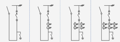 | ||||
Main electrical equipment | ހަމަކަށަވަރުންްް | 125,016,002,000 | |||
New circuit driver ZN85-40.5 | 1 | 1 | 1 | 1 | |
Current transformer LDBJ8(9)-35 | 2 | ||||
Grounding switch IN22-40.5/31.5 | 1 | 1 | 1 | 1 | |
use | Overhead out | Overhead out | Overhead out | Overhead out | |
Scheme number | 05 | 06 | 07 | 08 | |
Main wiring diagram | 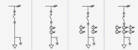 | ||||
Main electrical equipment | ހަމަކަށަވަރުންްް | 125,016,002,000 | |||
New circuit driver ZN85-40.5 | 1 | 1 | 1 | 1 | |
Current transformer LDBJ8(9)-35 | 2 | 3 | |||
Grounding switch IN22-40.5/31.5 | 1 | 1 | 1 | 1 | |
use | cable outlet | cable outlet | cable outlet | cable outlet | |
Scheme number | 09 | 10 | 11 | 12 | |
Main wiring diagram | 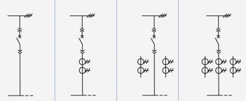 | ||||
Main electrical equipment | ހަމަކަށަވަރުންްް | 125,016,002,000 | |||
New circuit driver ZN85-40.5 | 1 | 1 | 1 | 1 | |
Current transformer LDBJ8(9)-35 | 1 | 2 | 3 | ||
use | Left (right) contact | Left (right) contact | Left (right) contact | Left (right) contact | |
Scheme number | 13 | 14 | 15 | 16 | |
Main wiring diagram | 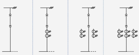 | ||||
Main electrical equipment | ހަމަކަށަވަރުންްް | 125,016,002,000 | |||
New circuit driver ZN85-40.5 | |||||
Current transformer LDBJ8(9)-35 | 1 | 2 | 3 | ||
use | contact | contact | contact | contact | |
Scheme number | 17 | 18 | 19 | 20 | |
Main wiring diagram | 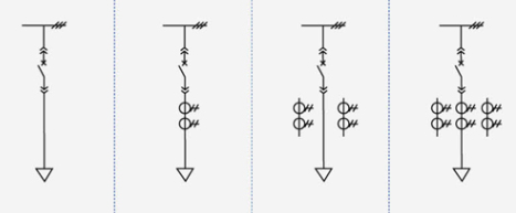 | ||||
Main electrical equipment | ހަމަކަށަވަރުންްް | 125,016,002,000 | |||
New circuit driver ZN85-40.5 | 1 | 1 | 1 | 1 | |
Current transformer LDBJ8(9)-35 | 1 | 2 | 3 | ||
use | Cable in | Cable in | Cable in | Cable in | |
Scheme number | 21 | 22 | 23 | 24 | |
Main wiring diagram | 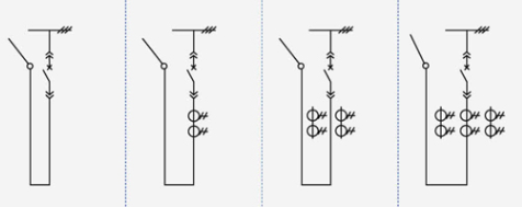 | ||||
Main electrical equipment | ހަމަކަށަވަރުންްް | 125,016,002,000 | |||
New circuit driver ZN85-40.5 | 1 | 1 | 1 | 1 | |
Current transformer LDBJ8(9)-35 | 1 | 2 | 3 | ||
use | Overhead in | Overhead in | Overhead in | Overhead in | |
Scheme number | 25 | 26 | 27 | 28 | |
Main wiring diagram | 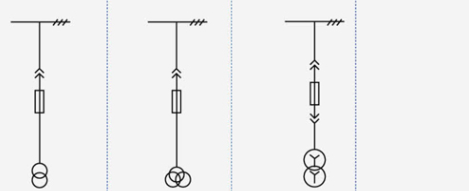 | ||||
Main electrical equipment | ހަމަކަށަވަރުންްް | 125,016,002,000 | |||
ފަހެًoltage transformer LDX9-35 | |||||
Fuse XPNP-35 | 2 | 3 | 2 | ||
Surge arrester YH5WS-51/134Q | 3 | ||||
| ޓްރަންސްޓަރް SCB9-50-35/0.4 | 1 | ||||
use | ފަހެًoltage transformer | ފަހެًoltage transformer | Station usage changed | ||
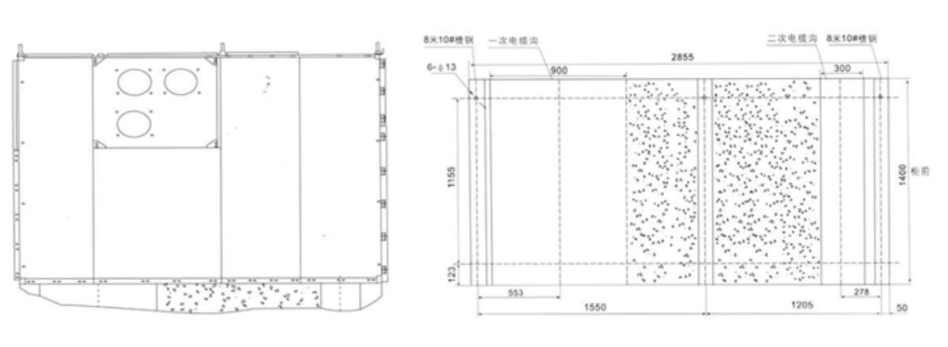
Dimensions and schematic diagram of Switchagerr structure
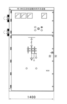 |  |
| Dimensions (WxDxH): 1400x2800x2600 | Schematic diagram of the structure of the Switchagerr ފަހެً relay instrument room B bus room C circuit breaker room D cable |
Switch cabinet installation
1. Height of electrical room: ≥4500mm:
2. Distance from the back of the cabinet to the wall: ≥1500mm;
3. Flatness of foundation frame: ≤1mm/m?;
4. The part of the foundation embedded channel steel above the ground shall not exceed 3mm;
5. It can be fixed on the foundation by bolting or welding:
6. The weight of the Switchagerr is about 1800Kg:
7. Width of the Switchagerr operation corridor (single row): ≥3000mm, double row (face to face) ≥ 4000mm.
އެއުރެންނަށްޓަކައި، consistency
the main scheme number of the secondary line, the single bus system diagram, the arrangement diagram and the layout diagram;
Secondary circuit electrical schematic diagram and terminal arrangement diagram:
the model, specification and quantity of electrical components of the Switchagerr;
Specifications and materials of main busbars and branch busbars:
Name and quantity of spare parts and spare parts:
Special requirements are agreed with the manufacturer.
އެއުރެންނަށްވުރެންނަށްވުރެންނަށްވުރެންނަށްވުރެންނަށްވުރެންނަށްވުރެންނަށްވުރެންނަށްވުރެން އަދި،އެއުރެންނަށްވުރެންނަށްވުރެންނަށްވުރެންނަށްވުރެންނަށްވުރެންނަ
Ordering instructions
The user should provide the following technical information when ordering:
އެއުރެންނަށްޓަކައި،އެއުރެންނަށްޓަކައި،އެއުރެންނަށްޓަކައި،އެއުރެންނަށްޓަކައި،އެއުރެންނަށްޓަކ އެއުރެންނަށްޓަކައި،އެއުރެންނަށްޓަކައި،އެއުރެންނަށްޓަކައި،އެއުރެންނަށްޓަކައި،އެއުރެންނަށްޓަކައި،އ
Indicate the specifications of the inlet and outlet cables.
Requirements for control, measurement and protection functions of Switchagerr and other requirements for latching and automatic devices.
އެއުރެންނަށްވުރެންނަށްވުރެންނަށްވުރެންނަށްވުރެންނަށްވުރެންނަށްވުރެންނަށްވުރެން ފަހެً އެއުރެންނަށްވުރެންނަށްވުރެންނަށްވުރެންނަށްވުރެންނަށްވުރެންނަށްވުރެންނަށްވުރެން އެއުރެންނަށްވުރެންނަށްވުރެންނަށްވުރެންނަށްވުރެންނަށްވުރެންނަށްވުރެންނަށްވުރެންނަށްވުރެންނަށްވުރެނ އެއުރެންނަށްޓަކައި،
When Switchagerr is used in special environments, it should be detailed at the time of ordering.
Other special requirements.
Schematic diagram of the installation of Switchagerr